
Home › Resources › Planetary Gearbox Guide
Planetary Gearboxes: An In-Depth Guide to Types, Applications, and Selection
A complete engineering reference covering how planetary gearboxes work, how to calculate gear ratios, how to read backlash specifications, how to select the right unit for your application, and how to keep it running. Written by the application engineers at Source Engineering Inc., supplying OEM motion control from Santa Clara, California since 1998.
1. What Is a Planetary Gearbox?
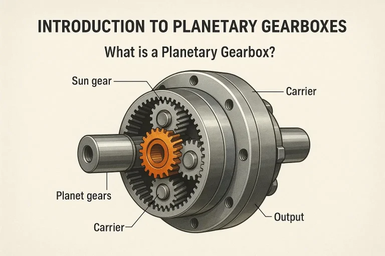
A planetary gearbox, also known as an epicyclic gearbox, is a gear system defined by a distinctive concentric arrangement of its components. Unlike a traditional parallel-shaft gearbox, where gears sit side by side on offset axes, a planetary gearbox places a central sun gear, an outer ring gear (also called an internal or annulus gear), and several planet gears that revolve around the sun while meshing with both the sun and the ring.
These planet gears are mounted on a movable carrier, which dictates their orbital motion. The name comes from this arrangement: the planet gears orbit the central sun gear much as planets orbit a star. This concentric layout allows load to be distributed efficiently among multiple gear meshes simultaneously, which is the root of nearly every performance advantage the architecture offers.
The primary function of a planetary gearbox is to provide significant torque multiplication and speed reduction within a remarkably compact envelope. Where a parallel-shaft gearbox transmits its entire load through a single point of tooth contact, a planetary gearbox with three planet gears divides that same load across three simultaneous meshes. Each tooth sees roughly a third of the stress, which means the unit can be built smaller, lighter, and stiffer for the same rated torque.
Planetary vs. parallel-shaft: the practical difference
Two characteristics matter most to a design engineer choosing between architectures.
The first is the coaxial shaft arrangement. In a planetary gearbox, the input and output shafts sit on the same centerline. A motor bolts directly to the input flange and the output shaft emerges from the opposite face along the same axis. There is no offset to design around, no jackshaft, no belt. For a robot joint, a linear actuator, or any assembly where the drivetrain has to disappear into a tube or a housing, this is decisive.
The second is torsional stiffness. Because load is shared symmetrically around the axis, radial forces on the bearings largely cancel out and the gear train resists twisting far better than an equivalent offset design. In a servo system, torsional stiffness governs how high you can set the position loop gain before the system becomes unstable. A stiffer gearbox means a faster, more responsive machine.
2. History and Evolution
The epicyclic gear principle is old. Its foundational geometry appears in ancient astronomical instruments and intricate mechanical clocks, where designers needed to model orbital motion and required compact, concentric gear trains to do it. The Antikythera mechanism and later medieval astronomical clocks both relied on epicyclic arrangements centuries before anyone described them mathematically.
The modern form emerged with industrialization, when demand arose for power transmission that was simultaneously powerful and compact. Early industrial designs struggled with two problems that remain the central engineering challenges of the architecture:
- Load distribution. The theoretical advantage of splitting load across three planets only materializes if all three actually share the load equally. Manufacturing tolerances mean one planet inevitably carries more than its share. Early gearboxes frequently failed at a single planet while the others showed almost no wear.
- Manufacturing precision. An internally toothed ring gear is considerably harder to cut accurately than an external spur gear, and the concentricity requirements between sun, carrier, and ring are unforgiving.
Progress since has come from three directions. Materials science delivered case-hardened alloy steels that tolerate far higher contact stress. Precision machining - particularly gear grinding and honing - brought tooth geometry within tolerances that make genuine load sharing achievable. And gear geometry refinement, especially profile and lead modification, allowed engineers to deliberately shape teeth so they deflect into correct contact under load rather than only at rest.
More recently, computer-aided design and finite element analysis have transformed the design process. Engineers can now model meshing behavior, predict stress concentrations, and optimize load sharing before cutting a single gear. Combined with advanced synthetic lubricants and improved sealing technology, this is why a modern compact planetary gearhead routinely delivers backlash under one arc-minute and efficiency above 97% - figures that would have been unattainable a few decades ago.
3. The Four Components
Every planetary gear set is built from four elements. Understanding what each does - and which one you hold stationary - is the key to understanding the entire architecture.
Sun gear
The central gear, positioned on the main axis. It meshes externally with the planet gears. In a speed-reduction configuration - by far the most common - the sun gear is the input, typically driven directly by a servo or stepper motor. In a speed-increasing configuration, such as a wind turbine drivetrain, the sun gear becomes the output.
Planet gears
Typically two or more gears that orbit the central sun gear while meshing simultaneously with the sun and with the ring gear. They are responsible for distributing the load and transmitting power. The number of planets directly affects load-carrying capacity and balance: three is the most common arrangement because three points define a plane and the gear set is naturally self-centering, but four- and five-planet designs are used where torque density must be pushed higher.
Ring gear (annulus / internal gear)
The outer component, cut with internal teeth that mesh with the planet gears. It encapsulates the sun and planets, forming the outer boundary of the gear set. The ring gear may be held stationary as a reaction member, driven as an input, or taken as an output, depending on the configuration.
Carrier (planet carrier / arm)
The structural element that holds the planet gears in position and maintains their spacing around the sun. Planet gears are mounted on shafts fixed to the carrier, allowing each planet to rotate on its own axis while simultaneously revolving around the sun. In the standard reduction configuration, the carrier is the output member and is connected directly to the output shaft.
4. How the Gears Interact
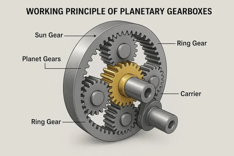
The operating principle depends on fixing one of the three main rotating members - sun, carrier, or ring - then designating one of the remaining two as the input and the third as the output. Which member you hold stationary determines the ratio, the direction of rotation, and whether the unit reduces or increases speed.
The standard reduction configuration
In the most common arrangement:
- Input: sun gear, motor-driven
- Stationary: ring gear, fixed to the housing
- Output: carrier
The sequence works like this. As the sun gear rotates, it drives the planet gears that mesh with it. Because those planet gears also mesh with the stationary ring gear, they cannot simply spin in place - they are forced to walk, or roll, along the inside of the ring gear. This rolling motion compels the planets to orbit the sun gear, carrying the carrier with them. The carrier therefore rotates far more slowly than the input sun gear, reducing speed and multiplying torque in the same proportion.
All three configurations compared
| Fixed member | Input | Output | Effect | Typical use |
|---|---|---|---|---|
| Ring gear | Sun | Carrier | Speed reduction, torque multiplication, same direction of rotation | Servo gearheads, robot joints, the overwhelming majority of industrial gearboxes |
| Carrier | Sun | Ring | Speed reduction with reversed direction of rotation | Applications requiring output rotation opposite to input |
| Sun gear | Ring | Carrier | Speed reduction, lower ratio than the standard configuration | Hub drives, wheel drives, rotating-housing designs |
A fourth possibility exists: if no member is held fixed and two are driven independently, the gear set becomes a differential, summing or splitting power between two inputs. This is the principle behind hybrid vehicle power-split devices and automotive limited-slip differentials.
Why load sharing produces the advantages
Three consequences follow directly from distributing load across multiple meshes:
- Increased load capacity. Torque is shared among the planet gears rather than carried by a single tooth pair, so the unit handles more torque for its size.
- Smoother operation. Multiple simultaneous contact points mean the transition as teeth engage and disengage is continuously overlapped rather than abrupt.
- Higher efficiency. The motion between meshing planetary gears is predominantly pure rolling rather than sliding, and rolling contact generates dramatically less friction than sliding contact. This is the central reason a planetary stage routinely exceeds 97% efficiency where a worm gear set might achieve 50–70%.
5. Gear Ratio Calculation
For the standard configuration - stationary ring gear, sun as input, carrier as output - the reduction ratio is given by:
Where Zr is the number of teeth on the ring gear and Zs is the number of teeth on the sun gear.
Worked example
Consider a gear set with a sun gear of 20 teeth and a ring gear of 80 teeth, with the ring gear fixed:
For every 5 rotations of the input sun gear, the output carrier rotates once. Speed is reduced by a factor of 5 and torque is multiplied by a factor of 5, ignoring efficiency losses. Accounting for a realistic 97% single-stage efficiency, actual output torque would be 5 × 0.97 = 4.85 times input torque.
Planet gear tooth count
The planet gear tooth count is not arbitrary - it is fixed by the geometry of the sun and ring:
In the example above: Zp = (80 − 20) / 2 = 30 teeth.
There is a second constraint. For the planet gears to be spaced evenly around the sun - which they must be, or the gear set will not be balanced - the sum of the sun and ring tooth counts must be divisible by the number of planets. With 20 + 80 = 100 teeth and three planets, 100 ÷ 3 is not an integer, so this particular combination cannot be assembled with three evenly spaced planets. It works with four (100 ÷ 4 = 25) or five (100 ÷ 5 = 20). This assembly condition is one of the reasons commercially available ratios cluster around particular values rather than being continuously selectable.
Why the practical ratio range is limited
The formula shows that increasing the ratio requires increasing the ring-to-sun tooth ratio. But the sun gear cannot shrink indefinitely - below a certain tooth count, teeth undercut and lose strength, and the sun gear shaft becomes too small to transmit the input torque. In practice this caps a single planetary stage at roughly 10:1, with 11:1 achievable in some designs. Ratios below about 3:1 are similarly impractical because the ring gear would become too small to enclose the planets.
This is why single-stage planetary gearboxes are effectively always found in the 3:1 to 10:1 range, and why anything higher requires staging.
Multi-stage ratios
When stages are connected in series, the total ratio is the product of the individual stage ratios:
Two 5:1 stages produce 25:1. Three stages of 5:1 produce 125:1. This multiplication is how planetary gearboxes reach ratios in the hundreds or thousands while remaining far more compact than an equivalent parallel-shaft design.
Efficiency multiplies the same way. A single stage at 97% becomes 0.97 × 0.97 = 94% across two stages, and roughly 91% across three. Backlash also accumulates - though not by simple addition, since the backlash of later stages is divided by the ratio of the stages ahead of them. In practice, the first stage dominates the output backlash figure.
6. Gear Ratio Calculator
Enter the tooth counts for your sun and ring gears to calculate the reduction ratio, the required planet tooth count, and whether the set can be assembled with evenly spaced planets.
Sun + ring (100) must divide evenly by the planet count for equal spacing.
Reduction ratio
5.00 : 1
Planet teeth (Zp)
30 teeth
Est. efficiency
97%
Even spacing
✗ not with 3
Efficiency estimate assumes 97% per stage, typical of a quality helical planetary stage. Actual figures depend on ratio, load, and lubrication - consult the relevant product catalog for rated values.
7. Types of Planetary Gearboxes
7.1 Single-stage planetary gearboxes
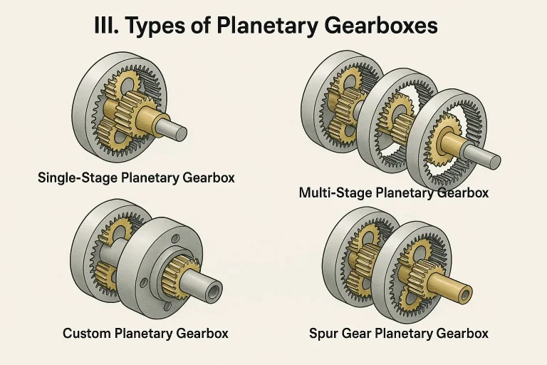
A single-stage planetary gearbox comprises one set of sun, planet, and ring gears with their corresponding carrier. The structure includes one central sun gear, several planet gears meshing with the sun, a planet carrier holding the planet gears, and an outer ring gear meshing with the planets.
Power is typically input through the sun gear, the ring gear is held stationary, and output is taken from the carrier. Key characteristics include extreme compactness, very high efficiency exceeding 97%, and reduction ratios limited to roughly 3:1 through 10:1 or 11:1.
Single-stage units suit small robotics, servomotor applications, and automated assembly lines where moderate speed reduction and high torque density in minimal space are essential. They also deliver the lowest backlash of any configuration - Source Engineering's SB Series achieves ≤1 arc-minute in single-stage ratios from 3:1 to 10:1.
7.2 Multi-stage planetary gearboxes
Multi-stage designs consist of two or more single planetary gear sets connected sequentially, with the carrier of one stage driving the sun gear of the next. The total gear ratio is the product of the individual stage ratios.
These systems achieve very high gear ratios, from 15:1 up to several hundred or even thousands to one. Overall length increases with each additional stage, though the unit remains relatively compact compared to a multi-stage parallel-shaft gearbox delivering the same ratio. While each stage maintains high efficiency, there is a small loss per stage; overall efficiency typically remains in the 90–95% range for multi-stage units.
Applications include heavy industrial machinery, wind turbines, solar tracking systems, large robotics, and construction equipment - anywhere extremely high torque and low output speeds are required.
| Characteristic | Single-stage | Multi-stage |
|---|---|---|
| Structure | One set of sun, planet, and ring gears | Two or more planetary gear sets in series |
| Reduction ratio range | Generally lower (3:1 to 11:1) | Very high (15:1 to hundreds or thousands:1) |
| Size | Extremely compact, shortest length | Relatively longer, but still compact compared to equivalent parallel-shaft gearboxes |
| Efficiency | Very high (typically >97%) | Slightly lower, but still very high (typically 90–95%) |
| Complexity | Relatively simpler | More complex in structure |
| Backlash | Lowest achievable (from ≤1 arc-min) | Higher; typically ≤3 arc-min and up |
| Typical applications | Small robots, servomotor drives, automated assembly lines, precision instruments | Wind turbines, solar tracking, heavy industrial machinery, large robots, construction equipment |
7.3 Spur gear planetary gearboxes
Spur gears feature straight teeth parallel to the axis of rotation - the most common and fundamental gear type. Their characteristics include simplicity and cost-effectiveness, being easier and generally less expensive to manufacture than helical gears; excellent efficiency in well-aligned systems; and the generation of only radial forces, with no axial thrust.
The notable trade-off is noise. Spur gear units can be noisier than helical gears, particularly at higher speeds, because the entire tooth line engages simultaneously - a phenomenon known as impact loading. They suit general industrial automation, power tools, and compact drive systems where efficiency and cost rank as primary considerations.
7.4 Helical gear planetary gearboxes
Helical gears have teeth cut at an angle to the gear face, forming a helix. The angled design enables gradual, progressive tooth engagement rather than simultaneous contact along the whole tooth.
The advantages follow directly. Operation is smoother and quieter because the angled teeth engage progressively from one end to the other. Load capacity improves because more teeth are in contact at any given moment, allowing a helical unit to handle higher loads than a spur unit of the same size.
The design consideration is axial thrust: helical gears generate a thrust force along the shaft, requiring appropriate thrust bearings to manage it. They are also more complex and expensive to manufacture.
Helical designs are chosen where noise reduction, vibration suppression, and higher load capacity are critical - high-precision robotics, high-speed machinery, automotive transmissions, wind turbine gearboxes, and heavy-duty industrial drives. Source Engineering's precision lines use helical-cut gears throughout, which is why they operate at 58–60 dB.
| Characteristic | Spur gear | Helical gear |
|---|---|---|
| Tooth shape | Straight teeth parallel to the axis | Angled (helical) teeth to the axis |
| Meshing method | Entire tooth line engages simultaneously | Gradual, progressive tooth engagement |
| Noise level | Higher, especially at high speeds | Quieter, smoother operation |
| Load capacity | Relatively lower for the same size | Relatively higher for the same size (more teeth in contact) |
| Axial thrust | None | Generates axial thrust; requires thrust bearings |
| Manufacturing complexity | Relatively simpler, lower cost | More complex, higher cost |
| Efficiency | High | Equally efficient, often slightly higher under appropriate conditions |
| Typical applications | General industrial automation, power tools, cost-sensitive applications | Precision robotics, high-speed machinery, automotive transmissions, noise-sensitive applications |
7.5 Inline vs. right-angle planetary gearboxes
Beyond gear tooth form and staging, planetary gearboxes divide into two output orientations, and the choice is usually dictated by the machine envelope rather than by performance.
Inline (coaxial) units place the output shaft on the same axis as the input. This is the native planetary configuration and delivers the best efficiency, the lowest backlash, and the highest torsional stiffness because power passes only through planetary stages.
Right-angle units add a bevel gear stage that turns the output 90° from the input. This allows a motor to be folded back alongside the machine rather than protruding from it - frequently the difference between a design fitting and not fitting. The trade-offs are real but modest: the added bevel stage costs a few points of efficiency and roughly triples or quadruples the backlash figure. A gearbox that achieves ≤1 arc-minute inline will typically specify ≤4 arc-minutes in its right-angle variant.
Manufacturers commonly indicate right-angle variants with a suffix. Across the Source Engineering range, R and WR denote right-angle bevel output - so SB is inline while SBR is right-angle, and SAE/SAF are inline while SAEWR/SAFWR are right-angle. Mounting flange shape is indicated separately: E for a round flange, F for a square flange.
7.6 Custom planetary gearboxes
Custom designs address highly specific application requirements that cannot be fulfilled by readily available solutions. Customization encompasses non-standard or extremely high or low gear ratios; specialized materials for extreme temperatures or aerospace use; specialized sealing and lubrication for unique environments; unique mounting configurations; ultra-low backlash requirements; noise reduction modifications; and units engineered for exceptionally long life or specific load cycles.
The benefit is precisely optimized performance for the intended application, often improving overall system efficiency, reliability, and longevity. Applications span high-precision scientific instruments, defense systems, specialized aerospace mechanisms, bespoke automated machinery, and medical devices where standard solutions prove insufficient.
Custom programs are often assumed to be prohibitively expensive, which is true when the base component cost is already high. Source Engineering approaches this from the opposite direction: by keeping standard component costs competitive, custom windings, ratios, shafts, and housings remain within reach of ordinary OEM budgets, and machined samples let you validate fit and form before committing to production. Talk to an application engineer about a custom program.
7.7 Planetary vs. other reducer architectures
Planetary is not the only way to reduce speed and multiply torque, and it is not always the right answer. Understanding where it sits against the alternatives clarifies when to specify it and when to look elsewhere.
Parallel-shaft (spur and helical) reducers place gears on offset axes. They are inexpensive, simple to manufacture, and perfectly adequate where the input and output do not need to be coaxial and torque density is not critical. They lose to planetary on size, stiffness, and backlash, and the offset shaft frequently forces awkward machine layouts.
Worm gear reducers achieve very high ratios in a single stage - 60:1 and beyond is routine - and offer an inherent right-angle output with, in many configurations, a self-locking characteristic that holds the load without power. The cost is efficiency: sliding contact between worm and wheel means 50–70% efficiency is typical, versus 97% for a planetary stage. That lost power becomes heat, which limits duty cycle. Worm units suit lifting, conveying, and holding applications where the self-locking behavior is worth the efficiency penalty. Source Engineering supplies both worm gearmotors and planetary units, and the choice usually comes down to whether self-locking matters.
Harmonic (strain wave) reducers use a flexible spline deforming inside a rigid circular spline to achieve extremely high ratios - 50:1 to 160:1 in a single very thin stage - with near-zero backlash. They are the standard choice for robot wrist joints and anywhere ratio-per-millimeter is the binding constraint. The trade-offs are cost, lower torsional stiffness than an equivalent planetary, limited peak torque capacity, and torque ripple from the flexspline. They are considerably more expensive per Nm than planetary units.
Cycloidal reducers use eccentric cycloidal discs engaging with pins rather than involute gear teeth. Because a large number of pins are in contact simultaneously, they tolerate shock loading exceptionally well and offer very high torque density with high ratios in a compact envelope. They are common in heavy robot base joints and applications with severe impact loading. They are more expensive than planetary and can exhibit slightly higher backlash than a precision planetary gearhead.
| Architecture | Typical ratio (single stage) | Efficiency | Backlash | Relative cost | Best suited to |
|---|---|---|---|---|---|
| Planetary | 3:1 – 10:1 | ≥97% | ≤1 arc-min and up | Low–moderate | Servo drives, robot joints, general precision motion - the default choice |
| Parallel shaft | 2:1 – 8:1 | 94–97% | 10–30 arc-min | Lowest | Cost-driven applications with no coaxial or precision requirement |
| Worm | 5:1 – 100:1 | 50–70% | 15–60 arc-min | Low | Lifting and holding where self-locking is valuable; right-angle by nature |
| Harmonic (strain wave) | 50:1 – 160:1 | 70–85% | <1 arc-min | High | Robot wrists, thin-profile joints, maximum ratio in minimum axial length |
| Cycloidal | 10:1 – 120:1 | 85–93% | 1–3 arc-min | High | Shock-loaded heavy robot base joints, high torque density with impact tolerance |
For the majority of OEM motion applications - a servo driving an axis, a joint, a conveyor, a positioning stage - the planetary gearbox wins on the combination of efficiency, stiffness, backlash, and cost that no other architecture matches simultaneously. The alternatives earn their place at the extremes: worm where self-locking matters, harmonic where axial length is the binding constraint, cycloidal where shock loading would destroy anything else.
8. Advantages of Planetary Gearboxes
High torque density
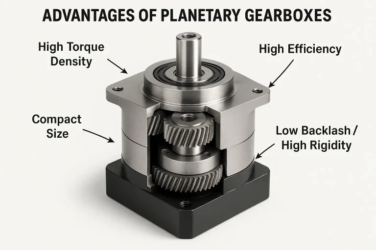
Distributing load among multiple planet gears allows higher torque transmission within a smaller volume. This load-sharing design means each gear tooth experiences reduced stress compared to conventional systems, enabling compact units to handle substantial power.
Compact size
The coaxial arrangement of input and output shafts, combined with concentric gear positioning, creates a space-efficient design and allows for smaller, lighter, more integrated machine designs. This is crucial for robotics and portable equipment, and eliminates the offset shaft complexities common in traditional gearboxes.
High efficiency
Primarily rolling contact between gear teeth minimizes friction and energy loss, often exceeding 95% per stage. The symmetrical load distribution and rolling motion reduce friction losses significantly, lowering energy consumption and heat generation during operation.
Why efficiency is really about heat
Efficiency is usually discussed as an energy cost, but in a sealed gearbox its more immediate consequence is thermal. Every watt not transmitted becomes heat inside the housing, and that heat has to leave through the case.
The arithmetic is straightforward. Heat generated equals input power multiplied by one minus efficiency:
A 750 W servo running continuously through a 97% efficient single-stage planetary generates about 23 W of heat - trivial for a metal housing to shed. The same motor through a 60% efficient worm reducer generates 300 W, which is a genuine thermal design problem requiring either a duty cycle limit, a larger housing, or forced cooling.
This is also why stacking stages carries a hidden cost. Three planetary stages at 97% each yield roughly 91% overall, turning 750 W of input into about 67 W of heat - nearly triple the single-stage figure. When a high ratio is achievable either through more planetary stages or a different architecture, the thermal consequence belongs in the comparison alongside size and cost.
Heat matters because lubricant degradation is temperature-driven. As a rough rule, grease life roughly halves for every 10 °C of sustained temperature rise. A gearbox running 20 °C hotter than necessary because it was undersized on thermal capacity may deliver a quarter of its expected service life while never once exceeding its torque rating.
| Advantage | Description | Key benefit for applications |
|---|---|---|
| High torque density | Distributes load among multiple planet gears, allowing higher torque transmission within a smaller volume. | Maximizes power output from a compact unit; enables heavy-duty applications in confined spaces. |
| Compact size | Coaxial input/output shafts and concentric gear arrangement save significant space compared to traditional gearboxes. | Allows smaller, lighter, more integrated machine designs; crucial for robotics and portable equipment. |
| High efficiency | Primarily rolling contact between gear teeth minimizes friction and energy loss, often exceeding 95% per stage. | Reduces energy consumption and operating costs; lower heat generation. |
| Low backlash / high rigidity | Symmetrical design and multiple meshing points provide excellent positional accuracy and torsional stiffness. | Essential for precise motion control, robotics, and accurate positioning systems. |
| Low noise & vibration | Load sharing and balanced rotation result in smoother operation with reduced noise and vibration levels. | Improves operational environment; reduces wear on components. |
| Coaxial design | Input and output shafts aligned on the same axis, simplifying machine integration. | Streamlines mechanical design; reduces system complexity. |
| Durability & long life | Robust construction and even load distribution across multiple gears enhance wear resistance and extend operational life. | Reduces maintenance frequency and costs; ensures long-term reliability. |
9. Understanding Backlash
Backlash is the single most misread specification on a gearbox datasheet, and for precision applications it is usually the one that decides the selection. It deserves its own treatment.
What backlash actually is
Backlash is the angular play, or lost motion, in the gear train - the amount the output shaft can rotate while the input is held stationary. It exists because gear teeth must have clearance between them to allow for lubrication, thermal expansion, and manufacturing tolerance. A gear set with genuinely zero clearance would bind and seize.
It is measured in arc-minutes. One arc-minute is 1/60 of a degree. To make that concrete: 1 arc-minute of backlash at the end of a 500 mm robot arm translates to approximately 0.145 mm of positional uncertainty at the tool. At 10 arc-minutes, that becomes about 1.45 mm.
Why it matters in a servo system
Backlash matters in two distinct ways, and engineers frequently consider only the first.
The obvious effect is positional error on direction reversal. When the drive reverses, the output does not move until the teeth cross the backlash gap. In a system doing unidirectional indexing this hardly matters. In a system that reverses constantly - a pick-and-place arm, a contouring CNC path - it appears directly in the finished part.
The subtler and often more damaging effect is on servo loop stability. Backlash introduces a nonlinearity between motor and load. During the moment the teeth are not in contact, the motor is effectively driving an unloaded shaft, then suddenly re-engages the full load inertia. High-gain position loops respond to this with a characteristic buzzing or hunting around the setpoint. The practical consequence is that excessive backlash forces you to detune the servo, which costs you the machine's responsiveness - a performance loss that never appears in the backlash number itself.
Reading precision grades
Manufacturers publish backlash in graded tiers rather than a single figure, because the same gearbox is offered in different precision classes. Source Engineering uses a P0 / P1 / P2 convention:
| Grade | Designation | 1-stage | 2-stage | Typical use |
|---|---|---|---|---|
| P0 | Super precision | ≤1 arc-min | ≤3 arc-min | Semiconductor positioning, metrology, precision robotics |
| P1 | Precision | ≤3 arc-min | ≤5 arc-min | Articulated robots, CNC axes, high-accuracy automation |
| P2 | Standard | ≤5 arc-min | ≤7 arc-min | General industrial automation, conveyors, material handling |
Two things to note when comparing datasheets. First, these are maximum values, not typical ones - a unit specified at ≤3 arc-min may measure considerably better. Second, adding a right-angle bevel stage increases backlash substantially: an inline unit rated ≤1 arc-min will typically specify ≤4 arc-min in its right-angle version. Compare like with like.
10. Selecting the Right Planetary Gearbox
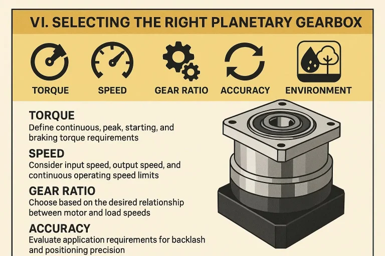
Torque requirements
Evaluate continuous operating torque, peak torque, and acceleration torque. The gearbox's rated output torque must exceed the application's continuous operating torque, and its maximum momentary torque capacity must withstand the application's peak or starting torques. These are two separate checks and a gearbox can pass one while failing the other.
Speed considerations
Define maximum input speed and required output speed. Continuous operating speed affects heat generation; exceeding the maximum rated input speed risks overheating and reduced lifespan. Most precision planetary gearheads are rated for 3,000 rpm continuous with a higher momentary maximum - the SB Series, for instance, is rated 3,000 rpm standard and 6,000 rpm in high-speed configuration.
Gear ratio
The ratio bridges motor speed and load speed requirements. Higher ratios may require multi-stage designs, which influences size, efficiency, backlash, and cost. Work out the ratio from the speed requirement first, then check that the resulting torque multiplication does not exceed the gearbox rating.
Accuracy (backlash)
Covered in detail in section 9. High-precision applications such as robotics and CNC require ultra-low backlash under 3 arc-minutes, while general industrial uses may tolerate 5–15 arc-minutes.
Environmental conditions
Consider operating temperature range, moisture and dust exposure (IP rating), vibration levels, and shock loads - all of which affect component selection, sealing, and lubricant choice. IP65 is standard across most precision planetary gearheads; washdown, vacuum, and high-temperature environments require specific attention.
Service factor
The service factor is a corrective coefficient based on load type, shock level, daily operating hours, starting frequency, and ambient conditions. Select a gearbox whose rated torque satisfies:
Typical service factors range from 1.0 to 2.0 and above depending on operating severity. A smoothly loaded unit running eight hours a day with few starts might use 1.0–1.2; a shock-loaded unit running continuously with frequent reversals might require 1.8–2.5.
Inertia matching
Load inertia reflected to the motor shaft should maintain a ratio typically between 3:1 and 5:1. The gearbox is the primary tool for achieving this, because reflected inertia is divided by the square of the gear ratio - a 10:1 gearbox reduces reflected load inertia by a factor of 100. Too high a ratio of load to motor inertia can lead to motor control instability, sluggish response, overheating, or vibration.
Thermal capacity
Thermal capacity is the maximum amount of heat a gearbox can dissipate continuously without internal temperature exceeding permissible limits. It is critical for continuous, high-speed operation. Insufficient thermal capacity accelerates lubricant degradation and component wear, and is a common cause of premature failure in units that appear adequately sized on torque alone.
| Selection factor | Key considerations | Impact / importance |
|---|---|---|
| Torque | Continuous, peak, starting, and braking torque requirements | Determines load capacity and lifespan; prevents overload damage. |
| Speed | Input/output RPM, maximum allowable input speed | Affects heat generation, noise levels, and output performance. |
| Gear ratio | Motor vs. load speed requirements, single or multi-stage | Influences final output speed, torque, and gearbox size. |
| Accuracy | Backlash in arc-minutes, positioning precision needs | Critical for system positioning and motion trajectory accuracy. |
| Environment | Operating temperature, IP rating, humidity, vibration, shock | Impacts reliability, sealing, lifespan, and material choice. |
| Service factor | Load type, operating hours, shock level | Modifies torque requirement to ensure margin for actual conditions, extending life. |
| Inertia | Load inertia, gearbox inertia, matching with motor inertia | Affects dynamic response, control stability, acceleration performance. |
| Thermal capacity | Heat generated during continuous operation, dissipation ability | Prevents overheating, protects lubricant and components; crucial for continuous duty. |
11. Worked Selection Example
A worked example makes the sequence concrete. Consider a cobot elbow joint with the following requirements:
- Required output torque, continuous: 45 Nm
- Peak torque during acceleration: 95 Nm
- Required output speed: 60 rpm
- Motor rated speed: 3,000 rpm
- Positional accuracy at the joint: ±0.05°
- Duty: continuous, frequent reversals, moderate shock
Step 1 - Determine the ratio
3,000 rpm ÷ 60 rpm = 50:1. That exceeds single-stage capability, so a two-stage unit is required. A standard 50:1 two-stage ratio is available in most precision ranges.
Step 2 - Apply the service factor
Continuous duty with frequent reversals and moderate shock suggests a service factor of approximately 1.5.
45 Nm × 1.5 = 67.5 Nm required rated output torque.
Step 3 - Check peak torque separately
The 95 Nm peak must fall within the gearbox's maximum momentary torque rating, which is typically around twice the continuous rating. A unit rated at 67.5 Nm continuous would generally permit roughly 135 Nm momentary - adequate.
Step 4 - Determine the backlash grade
±0.05° = ±3 arc-minutes total at the joint. The gearbox should consume no more than about half the error budget, leaving room for encoder resolution, structural deflection, and thermal drift. That points to ≤1.5 arc-minutes, so a two-stage P0 unit at ≤3 arc-min is marginal and P0 in a single-stage-dominant configuration is preferable.
Step 5 - Select the frame size
Cross-reference 67.5 Nm continuous at 50:1 against the torque tables. In the SB Series, this falls in the 090SB frame. Confirm the input adapter matches the motor's shaft diameter and pilot, and verify the output flange pattern against the joint housing.
Step 6 - Verify thermal and inertia
Confirm continuous operation at 3,000 rpm input is within the unit's thermal rating, and check that reflected load inertia divided by 50² keeps the motor inertia ratio under 5:1.
Send us your torque, speed, duty cycle, and accuracy requirements. Our application engineers will size the unit and confirm the mounting interface - no obligation.
Request a Quote (408) 980-982212. Mounting and Integration
A gearbox that meets every performance requirement is still useless if it does not bolt to your machine. Integration details account for a surprising share of late-stage design changes.
Input side: motor adapters
Precision planetary gearheads attach to the motor through a clamping collar and an adapter plate machined to the motor's pilot diameter and bolt pattern. A single gearbox frame size is typically available with a range of adapters covering common servo, stepper, BLDC, and PMDC motor faces. When specifying, confirm three dimensions: motor shaft diameter, pilot register diameter, and bolt circle. A mismatch in any one requires a custom adapter.
Output side: shafts and flanges
Output options generally include a smooth shaft with or without a key, a splined shaft, or an output flange for direct bolting. Flange output is preferred in robotics because it eliminates the compliance and backlash of a keyed coupling. Flange shape is often indicated in the model designation - across the Source Engineering range, E denotes a round mounting flange and F a square flange.
Mounting orientation
Most grease-lubricated precision planetary gearheads are rated for mounting in any orientation, which simplifies machine design considerably. Larger oil-lubricated units may specify an orientation, or require a different fill level and breather position depending on mounting angle. Check the catalog before designing a vertical-shaft installation.
Sealing and ingress protection
IP65 is the common standard for precision planetary gearheads, protecting against dust ingress and low-pressure water jets from any direction. This covers the great majority of factory environments. Food processing washdown, semiconductor vacuum, and outdoor solar tracking each impose requirements beyond IP65 and should be raised at the specification stage rather than discovered at installation.
13. Applications of Planetary Gearboxes
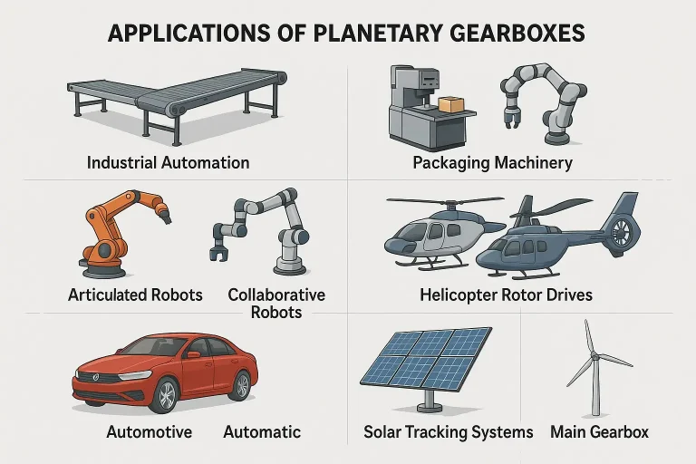
13.1 Industrial automation
Planetary gearboxes serve as a cornerstone for achieving precise and reliable motion control across factory automation systems.
- Conveyor systems - provide the torque and speed reduction for efficient, controlled movement of goods along production lines; compact design allows integration into space-constrained layouts.
- Packaging machinery - crucial for precise synchronization of fillers, sealers, and labelers, ensuring consistent product quality and high throughput.
- Printing equipment - essential for precise alignment and movement of rollers and plates, ensuring high-quality print registration.
- Material handling - automated guided vehicles, automated storage and retrieval systems, lifts and hoists requiring controlled movement and high load capacity.
- Cutting and welding machines - provide exact positioning and feed rates for intricate cutting paths and precise welding operations.
13.2 Robotics
Planetary gearboxes are almost synonymous with modern robotics due to their role in achieving the agility, strength, and precision robotic systems demand.
- Articulated robots - integrated into the joints of robotic arms to provide torque for lifting and manipulating heavy loads while maintaining positional accuracy.
- Collaborative robots (cobots) - low backlash and smooth operation support the precise, safe interaction required when working alongside human operators.
- Service robots - mobile platforms for navigation and locomotion, and manipulator arms across service industries.
- Exoskeletons - powered exoskeletons for medical rehabilitation or industrial assistance, providing joint torque for human augmentation.
- Humanoid robots - increasingly served by fully integrated joint modules combining motor, gearbox, encoder, and drive in a single drop-in assembly.
13.3 Aerospace and defense
The aerospace industry prioritizes weight reduction, reliability, and precision, making planetary gearboxes ideal.
- Aircraft actuators - control surface actuators for flaps, ailerons, and rudders; landing gear retraction; thrust reversers, where high torque in a compact, lightweight package is essential.
- Helicopter rotor drives - planetary stages are integral components of main rotor gearboxes due to their load-sharing capability and high reduction ratios.
- Satellite and spacecraft mechanisms - antenna pointing, solar array deployment, and robotic arms on space vehicles, where precise movement in extreme environments is paramount.
13.4 Automotive
- Automatic transmissions - multiple planetary gear sets provide various ratios without interrupting power flow, enabling smooth, seamless gear changes.
- Hybrid vehicle drives - power-split devices combine power from the internal combustion engine and electric motor for efficient energy management.
- EV drivetrains - single or multi-stage planetary gearboxes for optimal motor speed reduction and torque delivery to the wheels.
- Limited-slip differentials - planetary gear sets manage power distribution between wheels, enhancing traction.
13.5 Solar tracking systems
To maximize energy capture, solar panels must accurately track the sun throughout the day. Single-axis trackers drive panels to tilt along one axis, optimizing angle relative to the sun. Dual-axis trackers enable more complex movement, tracking both azimuth and elevation. The high precision and robustness of planetary gearboxes ensure reliable long-term operation in outdoor environments.
13.6 Wind turbines
Planetary gearboxes are a critical component in the drivetrain of most multi-megawatt wind turbines, bridging the slow-rotating rotor and the high-speed generator. The main gearbox connects slow-spinning rotor blades to the much faster generator, with planetary stages proving highly efficient for this substantial speed increase. Smaller planetary gearboxes also serve pitch systems controlling blade angle and yaw systems orienting the nacelle into the wind.
13.7 Packaging machinery
Packaging relies substantially on the precision and high cycle rates planetary gearboxes enable. Filling machines ensure accurate volume dispensing; sealing machines provide consistent pressure and timing; labeling machines guarantee precise label placement at high speeds; and cartoning and palletizing machines deliver controlled movements for forming, filling, sealing, and stacking. Low backlash and compact size are essential for the synchronized, high-speed operation characteristic of modern packaging lines.
13.8 Printing equipment
The printing industry demands high-quality, high-speed, consistent output. Offset presses use gearboxes in drive mechanisms for plate, blanket, and impression cylinders, requiring extremely precise registration to prevent ghosting or misprints. Digital presses benefit in paper feed mechanisms and print head positioning. Flexographic and gravure presses require accurate control of roller speeds and tensioning systems.
13.9 Semiconductor and medical
Two further sectors deserve mention. Semiconductor equipment demands the tightest positional accuracy of any industrial application - wafer handling, stage positioning, and metrology routinely specify P0-grade backlash. Medical devices, including surgical robotics, diagnostic equipment, and lab automation, combine precision requirements with stringent noise, cleanliness, and reliability constraints.
14. Maintenance and Troubleshooting
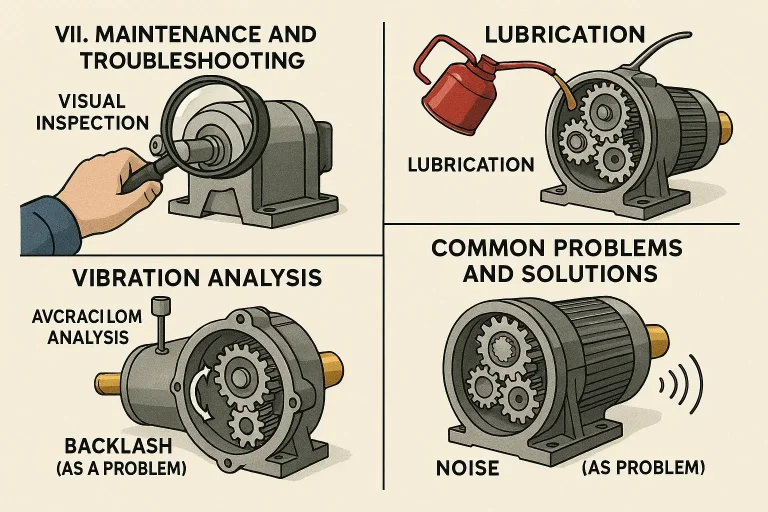
Proactive and scheduled maintenance is far more cost-effective than reactive repair.
Regular maintenance tasks
- Visual inspection for physical damage and lubricant leaks
- Lubricant level checks
- Assessment of lubricant condition for discoloration or contamination
- Verification of fastener tightness, particularly mounting bolts
- Keeping the gearbox exterior clean to support heat dissipation
Lubrication
Lubrication is arguably the single most critical factor in a planetary gearbox's longevity and performance. It serves four functions simultaneously: reducing friction and wear through protective films between moving parts; dissipating heat generated by friction; protecting against corrosion and moisture; and carrying away wear particles.
Lubricants come in two main types. Grease is used for smaller, sealed units - most precision planetary gearheads are grease-filled for life and require no scheduled lubrication at all. Oil is used for larger, high-speed applications, with application methods including oil bath, splash lubrication, and forced circulation systems. Adherence to the manufacturer's lubrication schedule is essential; over-filling is as damaging as under-filling, as excess lubricant churns and generates heat.
Vibration analysis
Vibration analysis is a predictive maintenance technique that monitors gearbox health through its unique vibration signature. Sensors detect changes indicating bearing wear, gear tooth defects, misalignment, imbalance, and component looseness. The benefits include reduced unplanned downtime through scheduled rather than emergency repairs, optimized maintenance intervals, and extended component lifespan.
Increased backlash
An increase in backlash over time indicates wear or damage. Causes include normal wear, bearing degradation, gear tooth damage, improper assembly, and shock loads. Symptoms include jerky motion and reduced positioning accuracy. For most high-precision, sealed planetary gearboxes, an increase in backlash usually means replacement of the gearbox rather than repair - the units are not designed to be field-serviceable and disassembly compromises the precision preload.
Unusual noise
Unusual noise indicates an underlying issue. Causes include insufficient or contaminated lubricant, worn bearings, damaged gear teeth, misalignment, overloading, and resonance. Solutions involve checking and replacing lubricant, inspecting for wear, realigning components, reducing load, and considering vibration isolation.
| Problem | Common causes | Possible solutions |
|---|---|---|
| Increased backlash | Normal wear, worn bearings, damaged gear teeth, overload, improper assembly | For sealed units, usually replacement of gearbox. For serviceable units, replace worn gears/bearings; verify assembly. |
| Excessive noise | Insufficient or contaminated lubricant, worn bearings, damaged gears, misalignment, overloading, resonance | Check/replace lubricant; inspect/replace worn bearings and gears; re-align motor and load; reduce load; consider vibration isolation. |
| Overheating | Overload, insufficient or incorrect lubricant, high speed, blocked ventilation, high ambient temperature | Reduce load; check lubricant level and type; ensure proper ventilation and cooling; replace if a design issue. |
| Oil leaks | Damaged seals, loose fasteners, excessive internal pressure, improper assembly | Replace damaged seals; tighten fasteners; check and clear breather valve; correct assembly procedures. |
| External vibration | Misalignment of motor or load, unbalanced components, loose mounting bolts | Re-align drive components; balance rotating parts; re-torque mounting bolts. |
| Reduced output torque | Overload, internal component wear or damage, motor issue, incorrect gear ratio | Check for overloading; inspect gears and bearings; verify motor function; re-evaluate gear ratio. |
| Shaft failure | Excessive peak or shock overload, fatigue, misalignment, improper material | Ensure gearbox is rated for peak loads; correct misalignment; consult manufacturer on material and design. |
15. Future Trends in Planetary Gearbox Technology
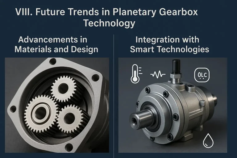
Advancements in materials and design
Materials science continues advancing toward higher strength-to-weight ratios through new steel alloys, ceramics, and composites - particularly important for aerospace and electric vehicle applications. Novel surface treatments and coatings, including advanced nitriding and diamond-like carbon (DLC) coatings, enhance durability and reduce friction. Research into smart, self-lubricating materials holds future promise.
Optimized gear geometry benefits from modern simulation. Computational tools including finite element analysis and computational fluid dynamics enable engineers to precisely model and simulate gear meshing, resulting in improved load sharing, reduced noise, and maximized efficiency. Additive manufacturing enables complex internal structures such as integrated cooling channels and customized designs without traditional tooling costs.
Integration with smart technologies
Future planetary gearboxes will feature embedded sensors monitoring temperature, vibration, speed, torque, and lubricant quality. Artificial intelligence and machine learning enable predictive maintenance by analyzing sensor data to anticipate failures before they occur, allowing proactive maintenance and minimizing unplanned downtime. Digital twin technology creates virtual replicas for real-time simulation and enhanced diagnostics.
Condition monitoring
Condition monitoring shifts maintenance from reactive or time-based approaches to predictive, condition-based strategies. Methods include vibration analysis, temperature monitoring, oil analysis for wear particles and contamination, and acoustic emission detection. Benefits encompass proactive maintenance, reduced unscheduled downtime, increased asset utilization, and extended component life.
IoT integration
Internet of Things connectivity enables gearboxes to transmit sensor data to cloud platforms for remote monitoring and diagnostics. IoT-enabled gearboxes integrate with enterprise resource planning systems, manufacturing execution systems, and computerized maintenance management systems, creating comprehensive factory visibility and facilitating data-driven decision-making across industrial operations.
16. Frequently Asked Questions
What is the maximum ratio of a single-stage planetary gearbox?
Approximately 10:1, with 11:1 achievable in some designs. Beyond that, the sun gear becomes too small to transmit input torque without tooth undercutting. Higher ratios require two or more stages connected in series, where the total ratio is the product of the individual stage ratios.
How do I calculate the gear ratio of a planetary gearbox?
For the standard configuration with a fixed ring gear, sun input, and carrier output, use i = 1 + Zr/Zs, where Zr is the ring gear tooth count and Zs is the sun gear tooth count. A 20-tooth sun and 80-tooth ring gives i = 1 + 4 = 5:1. Use the calculator above to work it out directly.
What does backlash in arc-minutes actually mean for my machine?
One arc-minute is 1/60 of a degree. At the end of a 500 mm arm, one arc-minute equals roughly 0.145 mm of positional uncertainty at the tool. Backlash also affects servo loop stability, since the nonlinearity it introduces forces lower position loop gains and a less responsive machine.
What is the difference between an inline and a right-angle planetary gearbox?
An inline gearbox places the output on the same axis as the input, delivering the best efficiency, lowest backlash, and highest stiffness. A right-angle gearbox adds a bevel stage turning the output 90°, which lets the motor fold alongside the machine. The trade-off is a few points of efficiency and roughly three to four times the backlash.
What do the letters in a gearbox model number mean?
Across the Source Engineering range, R and WR denote right-angle bevel output, E denotes a round mounting flange, and F denotes a square mounting flange. So SB is inline while SBR is right-angle; SAE is inline with a round flange while SAFWR is right-angle with a square flange.
Should I choose spur or helical gears?
Choose helical when noise, smoothness, or load capacity matter - precision robotics, high-speed machinery, anything in an occupied space. Choose spur when cost is the primary driver and moderate noise is acceptable. Helical gears generate axial thrust requiring thrust bearings, but the manufacturer handles this internally.
What service factor should I use?
Service factor depends on load type, shock level, daily operating hours, and starting frequency. Smooth loads running eight hours a day with few starts typically use 1.0–1.2. Continuous duty with frequent reversals and moderate shock suggests around 1.5. Severe shock loading with high start frequency can require 2.0 or more. Select a gearbox whose rated torque is at least the required torque multiplied by this factor.
Which motors can mount to a planetary gearbox?
Precision planetary gearheads accept servo motors, stepping motors, BLDC motors, and PMDC motors through standardized input adapters. Confirm three dimensions when specifying: motor shaft diameter, pilot register diameter, and bolt circle. Source Engineering supplies matching BLDC servo motors, stepping motors, and frameless servo motors alongside its gearboxes.
Can a planetary gearbox be repaired if backlash increases?
Usually not. Most high-precision sealed planetary gearheads are not field-serviceable - disassembly compromises the precision preload that produces the low backlash figure in the first place. An increase in backlash on a sealed unit normally means replacement. Larger serviceable units can have worn gears and bearings replaced.
How often does a planetary gearbox need lubrication?
Most compact precision planetary gearheads are grease-filled for life and require no scheduled lubrication. Larger oil-lubricated units follow a manufacturer-specified interval. In both cases, checking lubricant condition for discoloration or contamination during routine inspection is worthwhile, and over-filling should be avoided as excess lubricant churns and generates heat.
What IP rating do planetary gearboxes have?
IP65 is standard for precision planetary gearheads, protecting against dust ingress and low-pressure water jets from any direction - adequate for the great majority of factory environments. Washdown, vacuum, and high-temperature applications require specific attention at the specification stage.
What ratio do I need for an AGV or AMR drive wheel?
AGV and AMR drive applications typically require ratios in the 5:1 to 30:1 range, combining moderate reduction with high continuous torque and the ability to handle shock loads from floor irregularities. Source Engineering's SAGV Series is purpose-built for traveling wheel and lifting structures, covering 40–300 Nm across frame sizes 90, 95, and 115.
Explore Source Engineering Planetary Gearboxes
Source Engineering supplies nine motion control platforms to OEM programs in robotics, medical devices, semiconductor equipment, factory automation, and aerospace. Our planetary gearbox range spans economy through super-precision, inline and right-angle, with custom programs available at costs that stay within OEM budgets.
- High Precision Series - SB, SBR, SE, SER. Backlash from ≤1 arc-minute, efficiency ≥97%.
- Precision Economy Series - SAE, SAF, SAEWR, SAFWR, SBF, SBFWR. Precision and quality at an economy price.
- Economy Series - SEP, SEPR, SEPB, SEPRB, PNX. Cost-effective reduction for volume applications.
- Rotating Series - SD, SDR. Compact high-precision, 58–60 dB.
- AGV Series - SPG, SDPG, SRS, SAGV. Purpose-built for AGV and AMR drive and lift.
Talk to a Source Engineering application specialist. No obligations, just answers.
Request a Quote Download Catalogs (408) 980-9822